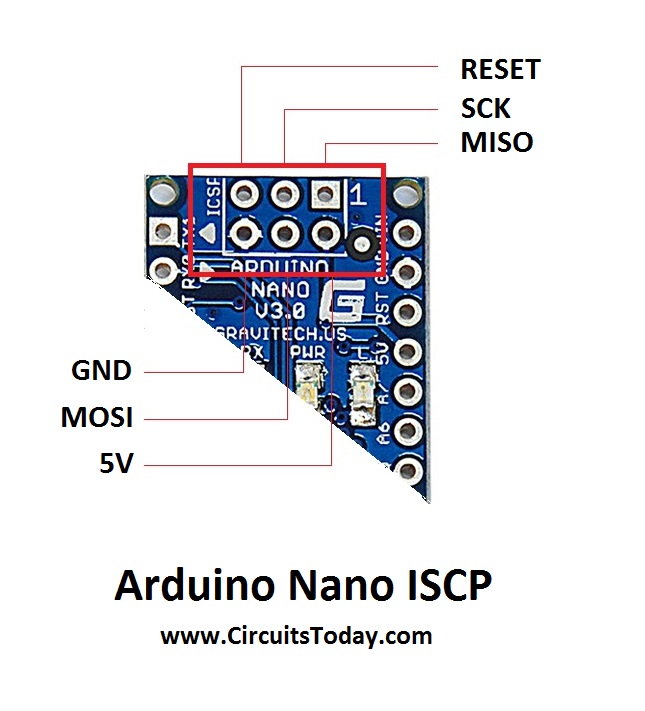

- #Arduino nano pinout diagram serial how to#
- #Arduino nano pinout diagram serial install#
- #Arduino nano pinout diagram serial code#
Lines 3 and 4 in the code above set the number of rows and columns on the keypad.

If you’re using a 3X4 keypad, you can use this code: #include Keypad customKeypad = Keypad(makeKeymap(hexaKeys), rowPins, colPins, ROWS, COLS) Once the Keypad library is installed, you can upload this code to the Arduino if you’re using a 4X4 keypad: #include Click on the library, then click install.
#Arduino nano pinout diagram serial install#
To install the Keypad library, go to Sketch > Include Library > Manage Libraries and search for “keypad”. This library takes care of setting up the pins and polling the different columns and rows. We’ll use the Keypad library by Mark Stanley and Alexander Brevig.
#Arduino nano pinout diagram serial how to#
Programming the Keypadįor a basic demonstration of how to setup the keypad, I’ll show you how to print each key press to the serial monitor. Repeat this process for each one of the other columns until you have each one mapped out. Now press down another button in the same row, and insert the positive wire into each one of the other pins.

The pin that makes the LED light up is the pin that’s connected to that button’s column. Now insert the positive wire into each one of the remaining pins. Now press and hold any one of the buttons in that row. To figure out which pins the columns are connected to, insert the ground wire into the pin you know is row 1. Now move the ground wire over to the next pin, press a button in a different row, and repeat the process above until you’ve found the pin for each row. If the LED lights up on a different pin, it means the ground wire is inserted into the row 1 pin. If none of the buttons in row 1 make the LED light up, the ground wire is not connected to row 1. If the LED lights up at one of the pins, press and hold another button in row 1, then insert the positive wire into each one of the other pins again. Now insert the positive (red) wire into each one of the other pins. Press any button in row 1 and hold it down. Insert the ground (black) wire into the first pin on the left. These logics will be implemented by the Arduino program.First, find out which keypad pins are connected to the button rows. Else if Arduino reads LOW(0) data from the sensor output pin, LED1(Green) will turn ON, and LED2(Red) will turn OFF, It means that it is Light. That is If Arduino reads HIGH(1) data from the sensor output pin, LED2(Red) will turn ON, and LED1(Green) will turn OFF, it means that it is dark. The LED1 (Green) and LED2 (Red) are uses as indicators, where the LED1 (Green) indicates and the LED2(Red) indicates the dark. The LDR sensor gives logic LOW (0) as digital output when light falls on the surface of the LDR, and it will give logic HIGH (1) digital output when no light falls on the surface of the LDR. In this circuit, the Sensor digital output pin is connected to the Arduino digital pin “D2”. How the LDR Sensor Works as a Dark & Light Detector Arduino LDR Sensor Circuit diagram for Digital Outputĭark & Light Detector using Arduino LDR Sensor Circuit Diagram Circuit Wiring Components Pin We have used 2 colors of LEDs, the Red LED is used to indicate Darkness and the green LED is used to indicate Light. Here the LDR sensor used to detect light and dark. In this part, we will learn how to make a dark & light detector project using the LDR sensor module and Arduino. LDR Sensor Output on Serial Monitor Window Dark & Light Detector


 0 kommentar(er)
